ShapeScript
Paths
A path is a sequence of line segments or curves joined end-to-end. The points of the path can be positioned anywhere in 3D space, and the path can be open-ended or closed.
Paths are not typically used directly as part of a scene (except possibly for something like a thin rope or antenna), but they can be used to define the contours or profile of a 3D shape (see builders for details).
Points
As with the polygons in a mesh, you define a path using a series of points. A path must have at least two points to be visible. The following path defines a short, horizontal line along the X axis.
path {
    point -1 0
    point 1 0
}

In the above example we used the point command, which accepts a vector value. Paths can be three-dimensional, so point accepts up to three coordinates, but most paths that you create in practice will be 2D (all points will have a Z value of zero).
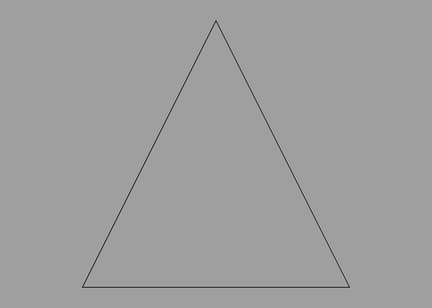
Paths can be open or closed (meaning that the points form an unbroken loop). To create a closed path, the first and last point must have the same position. The following path has four points, but it actually describes a triangle rather than a quadrilateral, because the first and last points are the same:
path {
    point 0 1
    point -1 -1
    point 1 -1
    point 0 1
}
Curves
Points are great for defining polygonal shapes, but what about curves?
Curves in ShapeScript are typically created using quadratic Béziers. A quadratic Bézier is defined by two end-points and a control point.
The curve passes through the end-points, but does not pass through the control point. Instead, the control point defines the point of intersection for the tangents of the curve as it passes through the end-points. This sounds complicated, but it’s quite straightforward to use in practice.
To create a smooth curve, use the point command to define end points, and the curve command to define control points. For example, the following creates a smooth arc:
path {
    point -1 -1
    curve 0 1
    point 1 -1
}
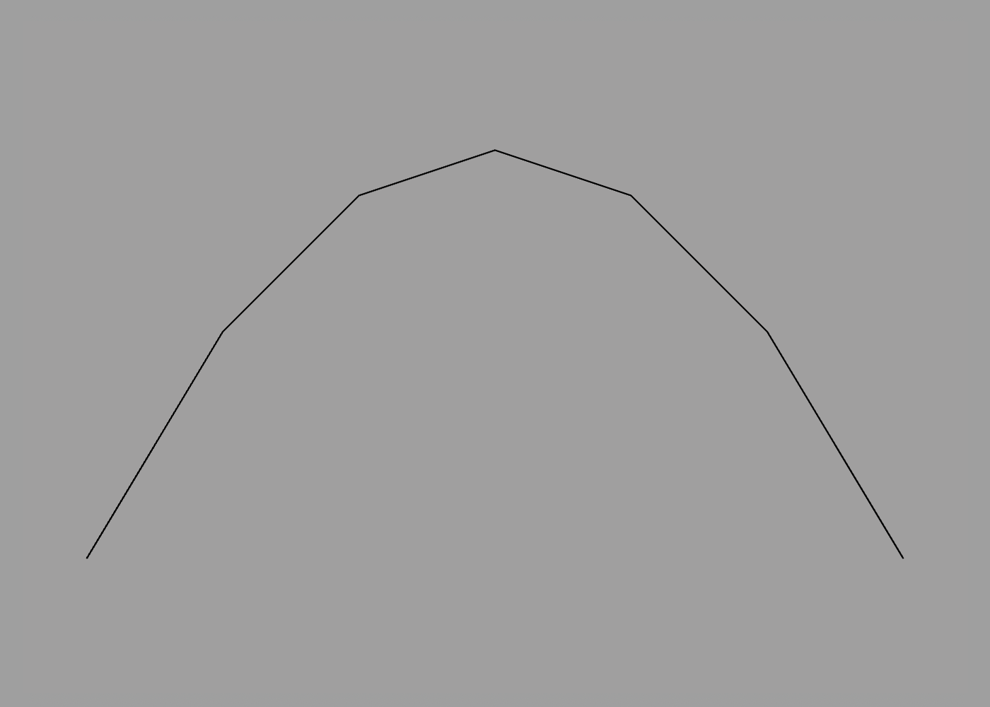
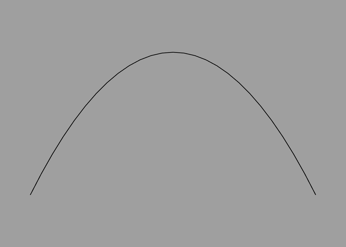
You may notice that this “smooth” arc is not actually very smooth. Just as 3D meshes are constructed from flat polygons, curves are approximated using straight lines. You can adjust the smoothness of curves in a path using the detail command:
path {
    detail 99
    point -1 -1
    curve 0 1
    point 1 -1
}
If multiple curve commands (control points) are used in sequence, an end-point will be interpolated at the mid-point between them. This allows you to easily create complex curves such as an “S” shape.
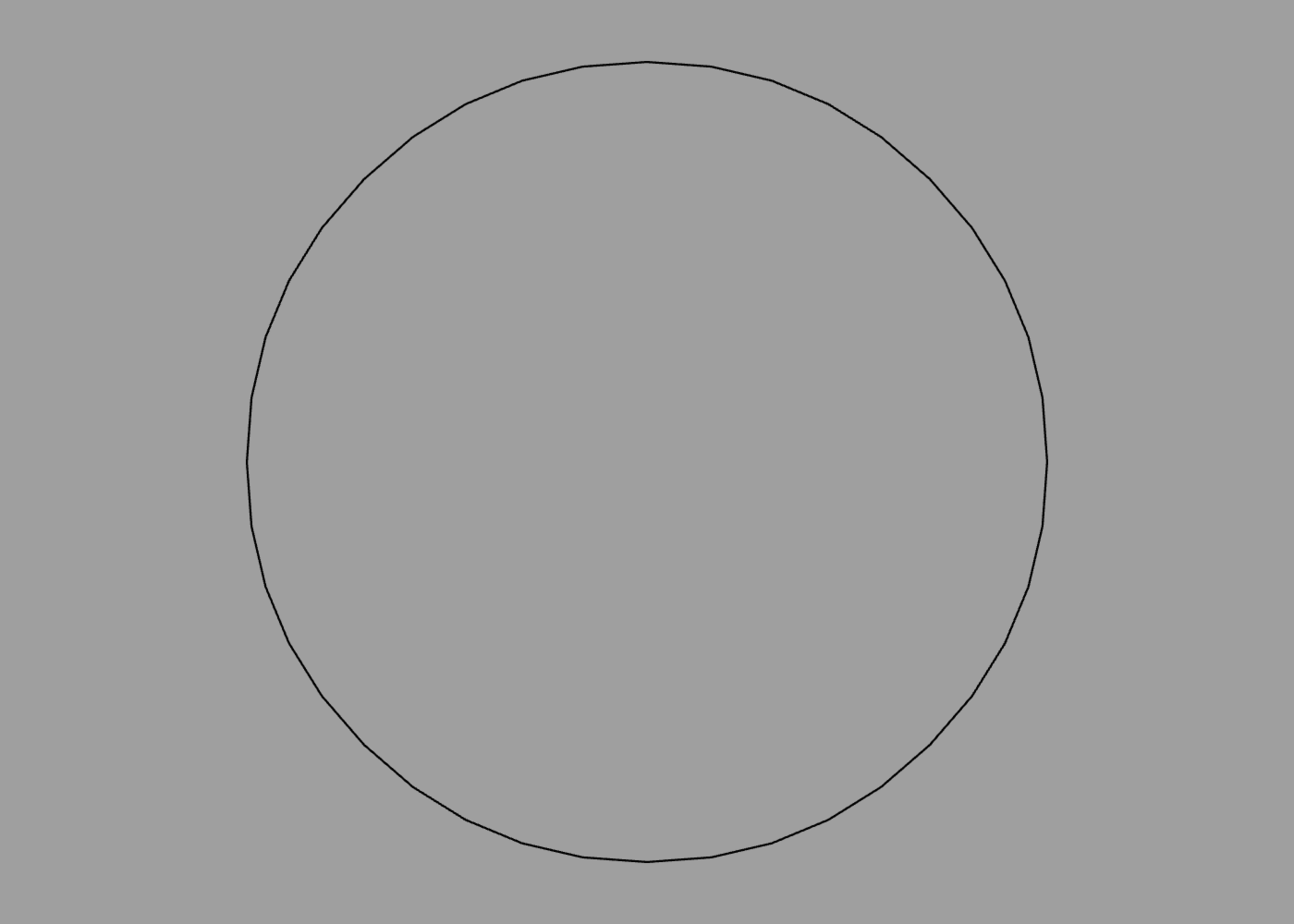
You can also create closed paths entirely using curve points. Eight curve points arranged in an octagon can closely approximate a circle (the ninth point is just a duplicate of the first, to close the path):
path {
    curve -0.414 1
    curve 0.414 1
    curve 1 0.414
    curve 1 -0.414
    curve 0.414 -1
    curve -0.414 -1
    curve -1 -0.414
    curve -1 0.414
    curve -0.414 1
}
Arcs
Arcs created by Bézier curves can approximate a circle, but not perfectly. If you need a precisely circular curve, you can use the arc command:
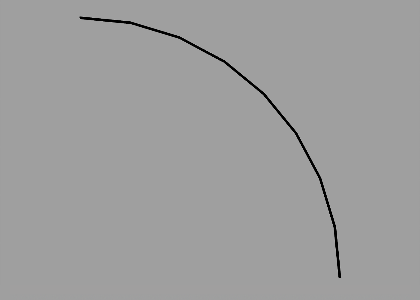
arc {
    angle 0.5
}
The angle option defines the angular span of the arc, starting clockwise from the Y axis. The angle is measured in half-turns (as explained in the Transforms section) so the 0.5 in the example above produces a quarter circle:
To adjust the starting angle, you can use the orientation option or rotate command as you would for any other shape. The following creates an arc from -45 degrees to +90 degrees:
arc {
    orientation -0.25
    angle 0.75
}
Arcs have a default radius of 0.5 units. You can increase or decrease this using the size option:
arc {
    size 2 // radius of 1 unit (0.5 * 2)
}
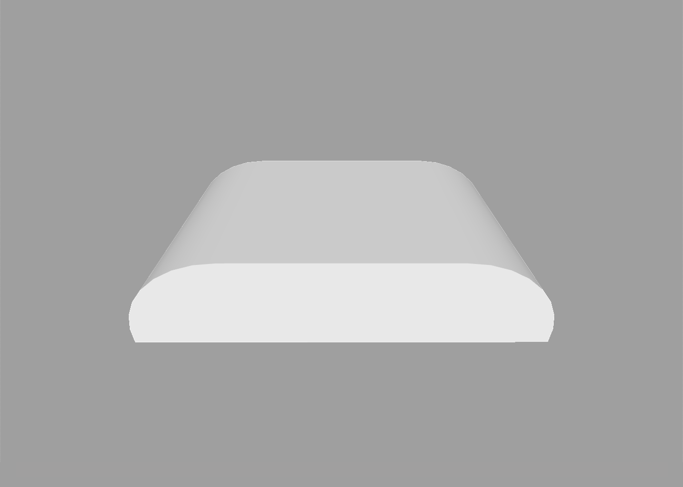
Arcs can be used in conjunction with individual path points or other arcs to make more complex shapes. The following creates a slab with curved corners:
extrude path {
    // left arc
    arc {
        angle -0.5
    }
    // bottom-left corner
    point -0.5 0
    // bottom-right corner
    point 1.5 0
    // right arc
    arc {
        position 1 0
        orientation 0.5
        angle -0.5
    }
    // close path with smooth join
    curve 0 0.5
}
Circles
If you need a complete circle, there’s an even simpler way than using arc, which is to use the circle command:
circle
Like the sphere primitive, the circle path has a default diameter of 1 unit, and its smoothness is controlled by the current detail setting, but these can both be overridden by passing explicit size and detail options:
circle {
    size 2
    detail 64
}
Rectangles
To create a square or rectangle you can use the square command:
square
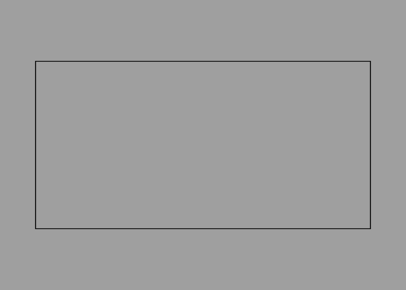
Like circle, square accepts a size option. The following will create a rectangle exactly twice as wide as it is tall:
square {
    size 2 1
}
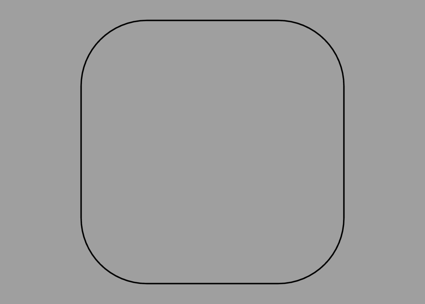
You can even create a rectangle with rounded corners using the roundrect command:
roundrect
In addition to size, roundrect also accepts a radius option, which controls the corner radius as a proportion of its size. If the size is non-uniform, the radius is proportional to the smallest dimension. For example, a radius of 0.25 is one quarter of the rectangle’s smallest dimension:
roundrect {
    size 1
    radius 0.25
}
Regular Polygons
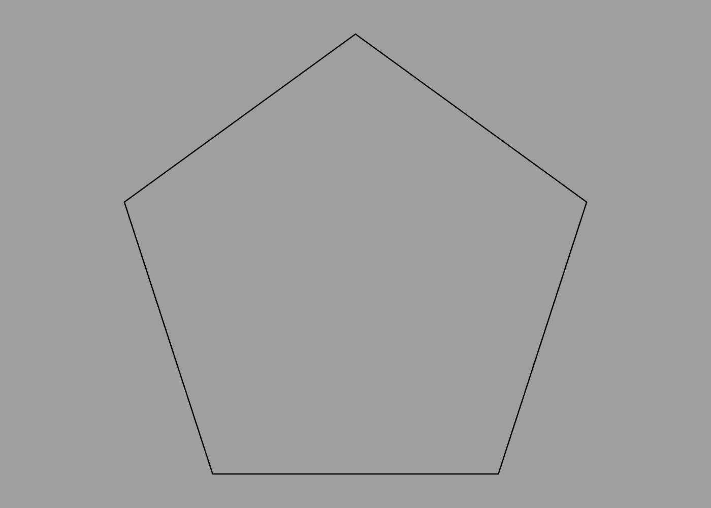
When used outside of a mesh, the polygon command can be used to create a regular polygon. The following creates a pentagon:
polygon {
    sides 5
}
The output for this is similar to using the circle command with a specific detail value:
circle {
    detail 5
}
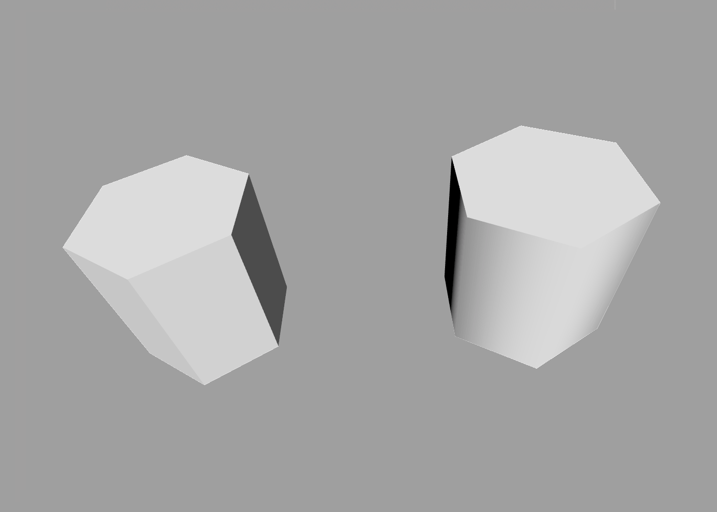
The difference is only apparent if you extrude the result, because in the circle’s case the extruded sides are smoothed by default, whereas for the polygon they are sharply defined:
extrude polygon {
    position -1
    sides 6
}

extrude circle {
    position 1
    detail 6
}
Procedural Paths
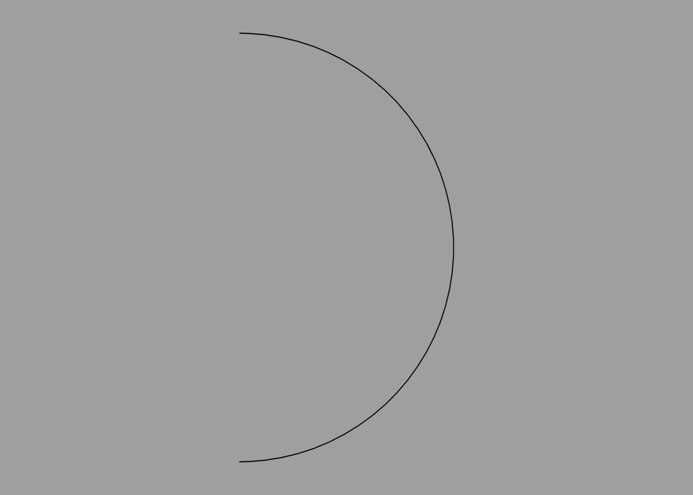
The circle command is fine for creating complete circles, but what if you want a circular arc or semicircle? Calculating the Bézier control points for that manually would be tedious, so this is where the power of ShapeScript’s procedural logic comes in handy.
To create a path procedurally, you can use a for loop along with relative transform commands such as rotate. For example, the following code generates a semicircle:
path {
    for 0 to 8 {
        curve 0 1
        rotate 1 / 8
    }
}
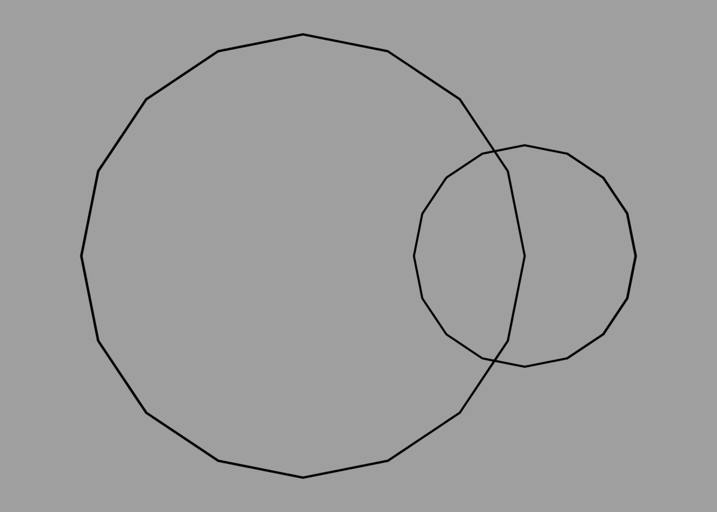
Nested Paths
A path can be formed from multiple distinct sub-paths. To add additional sub-paths, you can nest a path command inside another one (or any other command that returns a path). The following code creates a path made up of two overlapping circles:
path {
    circle
    translate 0.5
    scale 0.5
    circle
}
Path Colors
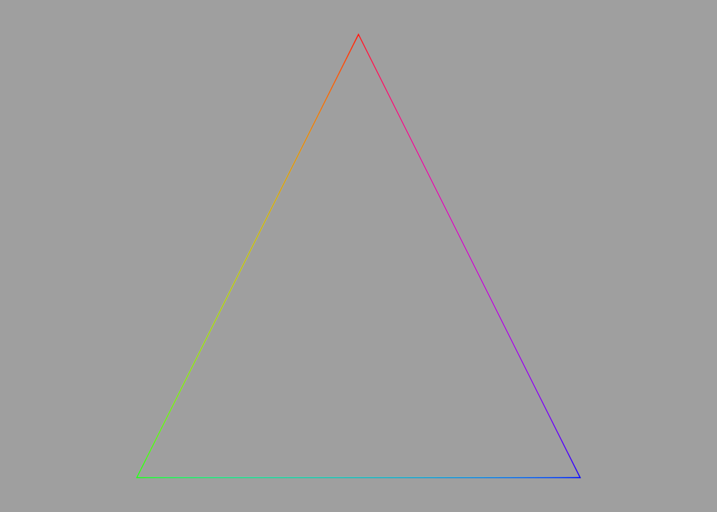
Paths cannot currently be textured, but they inherit the current material color. Color can also be applied to individual points within a path. When neighboring path points have different colors applied, the color will be smoothly interpolated between them, creating a gradient:
path {
    color red
    point 0 1
    color green
    point -1 -1
    color blue
    point 1 -1
}
SVG Paths
Scalable Vector Graphics (SVG) is a popular standard for defining vector graphics. SVG is a fairly complex XML-based format, but a subset of the SVG standard defines a simple text-based path syntax that uses a series of single-character instructions, each followed by one or more coordinates to define a path. For example, the following SVG path code defines a triangle:
<path d="M 100 100 L 300 100 L 200 300 z"/>
You can use this syntax in ShapeScript by taking just the d attribute from the path and passing it to the svgpath command, as follows:
fill svgpath "M 100 100 L 300 100 L 200 300 z"
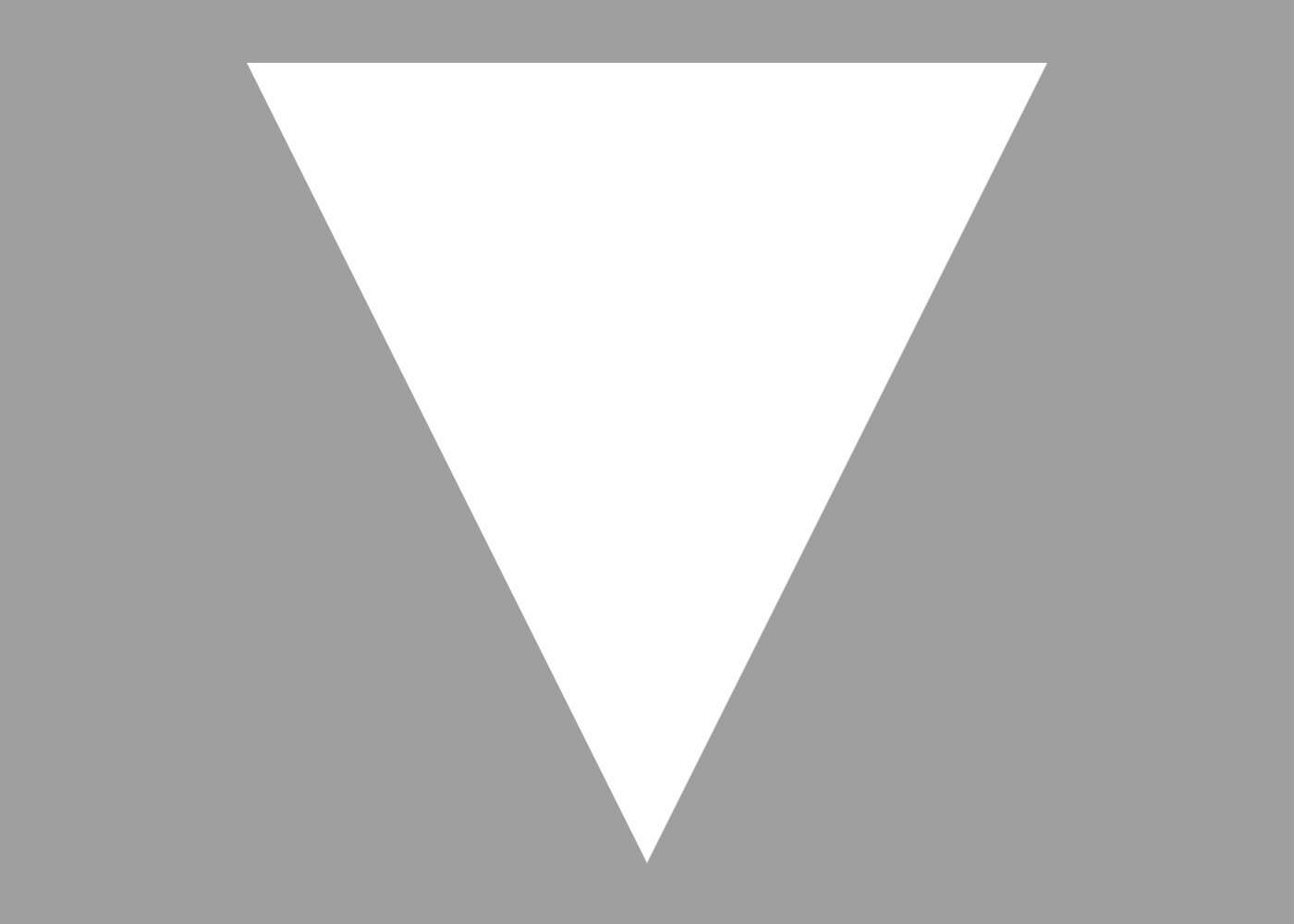
You can fill or extrude an svgpath and adjust its size, position, etc. as follows:
fill svgpath {
    size 0.01
    position -2 2
    "M 100 100 L 300 100 L 200 300 z"
}
Which produces the following output:
Note: SVG uses a flipped vertical coordinate system relative to that used by ShapeScript. To compensate for this, vertical (Y) coordinates passed to the svgpath command are treated as negative.