ShapeScript
Builders
We explored some basic 3D shape types in the primitives section, but the real power of ShapeScript comes from the ability to define custom shapes.
In the paths section we looked at how to define custom shapes using paths. ShapeScript has a variety of built-in commands for creating 3D shapes from paths, called builders:
Fill
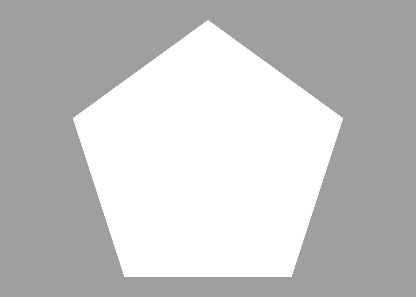
The most basic shape builder is the fill command, which creates a filled polygon from a path. Using the pentagon path we defined earlier, we can use fill to create a solid pentagon:
fill path {
    for 0 to 5 {
        point 0 1
        rotate 2 / 5
    }
}
Unlike a path, a filled shape can have a color and texture, but it has zero thickness.
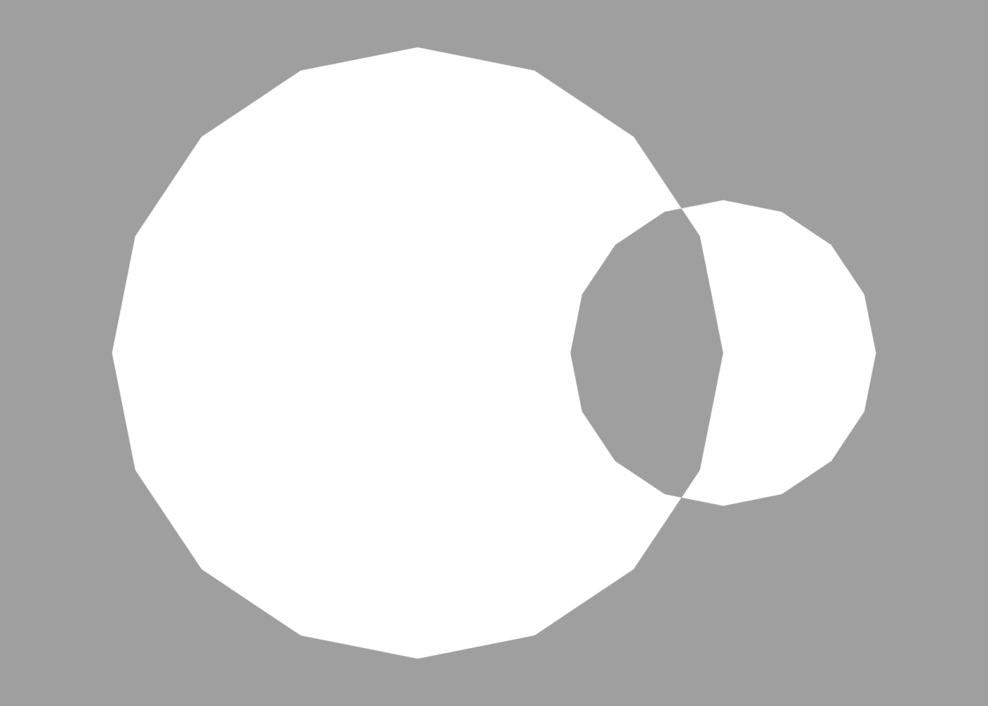
If a path contains multiple overlapping sub-paths, they will be filled using the even-odd rule. For example, the overlapping circles path would be filled like this:
fill path {
    circle
    translate 0.5
    scale 0.5
    circle
}
Lathe
The lathe command creates a 3D shape from a 2D path by revolving it around the Y axis.
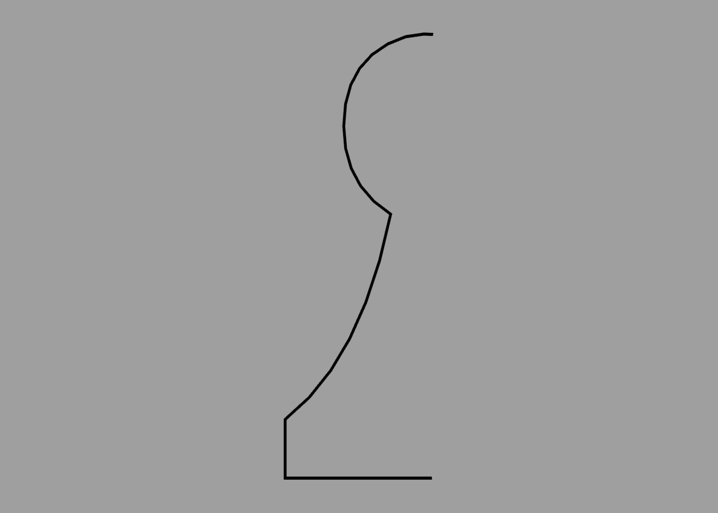
To use lathe, you must first define a suitable path. For example, the following code defines the profile (one half of the outline) of a chess piece:
path {
    curve 0 0.78
    curve -0.15 0.7
    curve -0.15 0.5
    point -0.07 0.45
    curve -0.12 0.2
    point -0.25 0.1
    point -0.25 0
    point 0 0
}
When passed to the lathe command, the path creates a solid 3D shape:
lathe path {
    curve 0 0.78
    curve -0.15 0.7
    curve -0.15 0.5
    point -0.07 0.45
    curve -0.12 0.2
    point -0.25 0.1
    point -0.25 0
    point 0 0
}
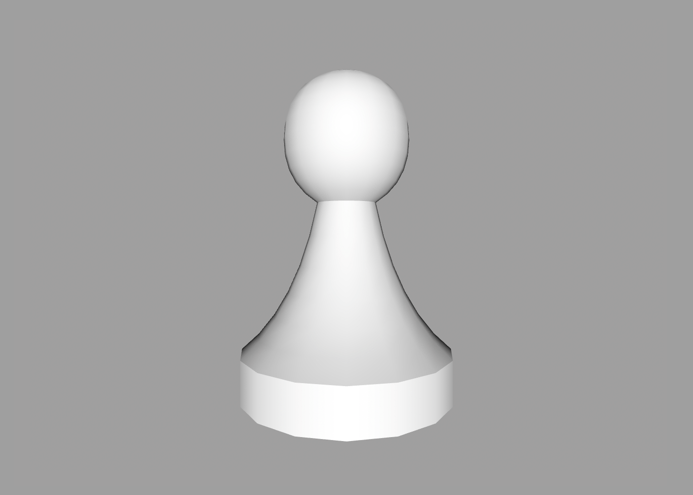
As with other curved shapes such as the sphere and cone, the smoothness of the lathed surface can be controlled using the detail and smoothing commands.
The path describing the profile of the lathed shape was in this case open-ended. Since the ends meet at the Y axis anyway, the resultant shape will still be closed. Open paths that do not touch the axis will produce a hollow shape with visible holes.
Lathed paths must lie flat on the XY plane, and be positioned entirely to one side of the Y axis. Any points on the path with a non-zero Z coordinate will be flattened, and parts of the path that cross the Y axis will be clipped before lathing.
Extrude
The extrude command extrudes a 2D path along the Z axis. The path therefore represents a cross-section of the final shape. The default extrusion distance is 1 unit, but it can be overridden using the size option or relative scale command (as described in transforms).
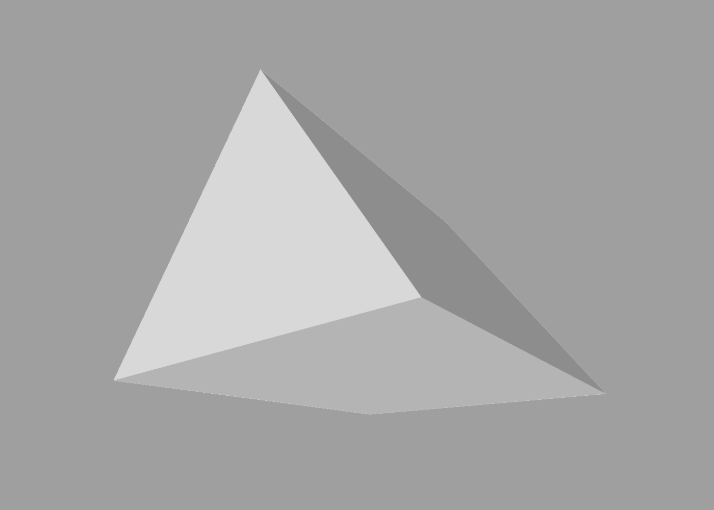
In the following example, extrude is used to create a triangular prism:
extrude {
    size 1 1 2 // increase extrusion distance to 2 units
    polygon { sides 3 }
}
You can also extrude a shape along another path using the along option. In the following example, a circle is extruded along a rounded rectangle:
extrude {
    circle
    along roundrect {
        size 5
    }
}
In the following example, we extrude a square cross-section along a 3D path:
define shape path {
    orientation 0 0 -0.4
    curve 0 1 0.75
    curve -1 0
    curve 0 -1 0.25
    curve 1 0
    curve 1 1
    curve 0 1 0.75
}

extrude {
    square { size 0.1 }
    along shape
}
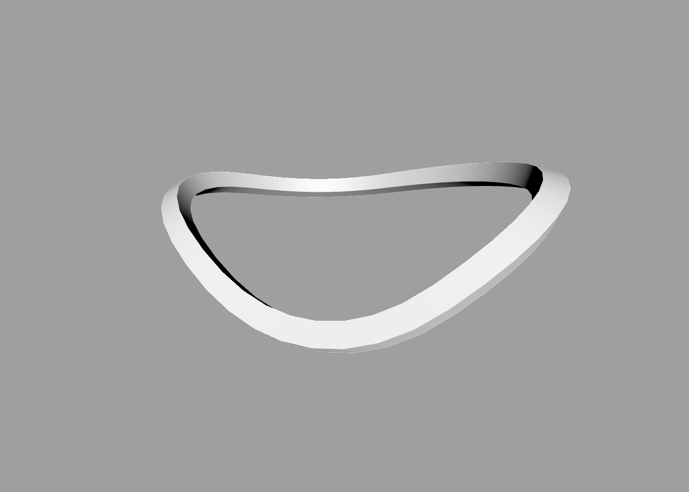
Note how the cross-section tilts as it follows the path. This can be a nice effect, but you might prefer that the cross section remains perpendicular to the world axes. To control this, you can use the axisAligned property:
extrude {
    square { size 0.1 }
    along shape
    axisAligned true
}
A value of true for axisAligned means the cross section will remain perpendicular to the path, which in some cases may cause the shape to look “pinched”.
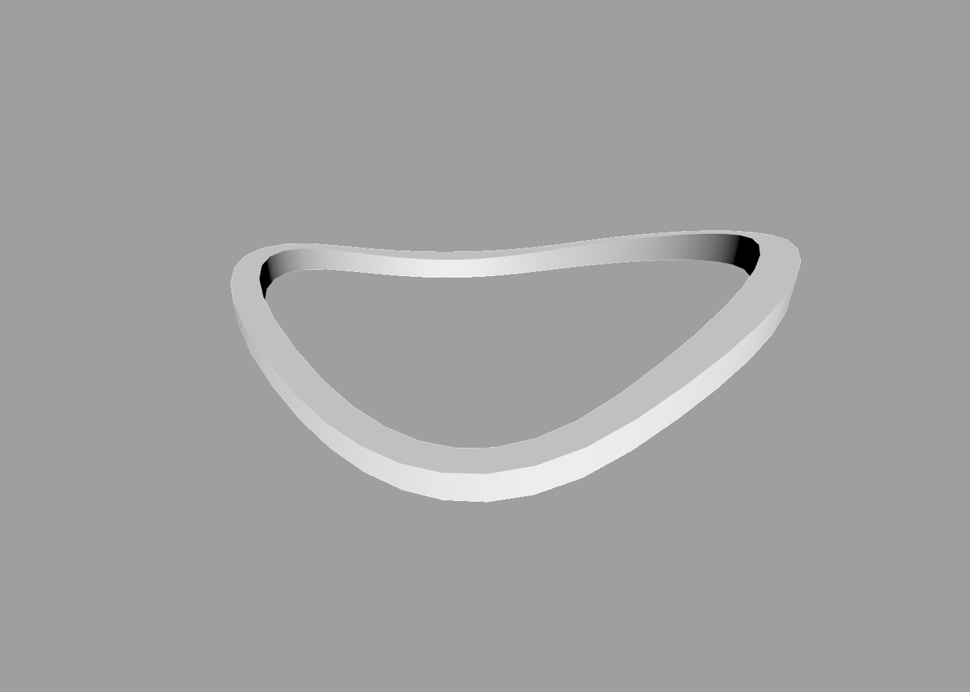
A value of false means the cross-section is always aligned to the tangent of the path, which ensures consistent thickness at the cost of inconsistent orientation.
If the axisAligned property is omitted, ShapeScript will try to choose an appropriate alignment for the path provided to along.
To apply a twist along the length of an extruded shape, you can use the twist property:
extrude {
    square
    twist 0.5
}
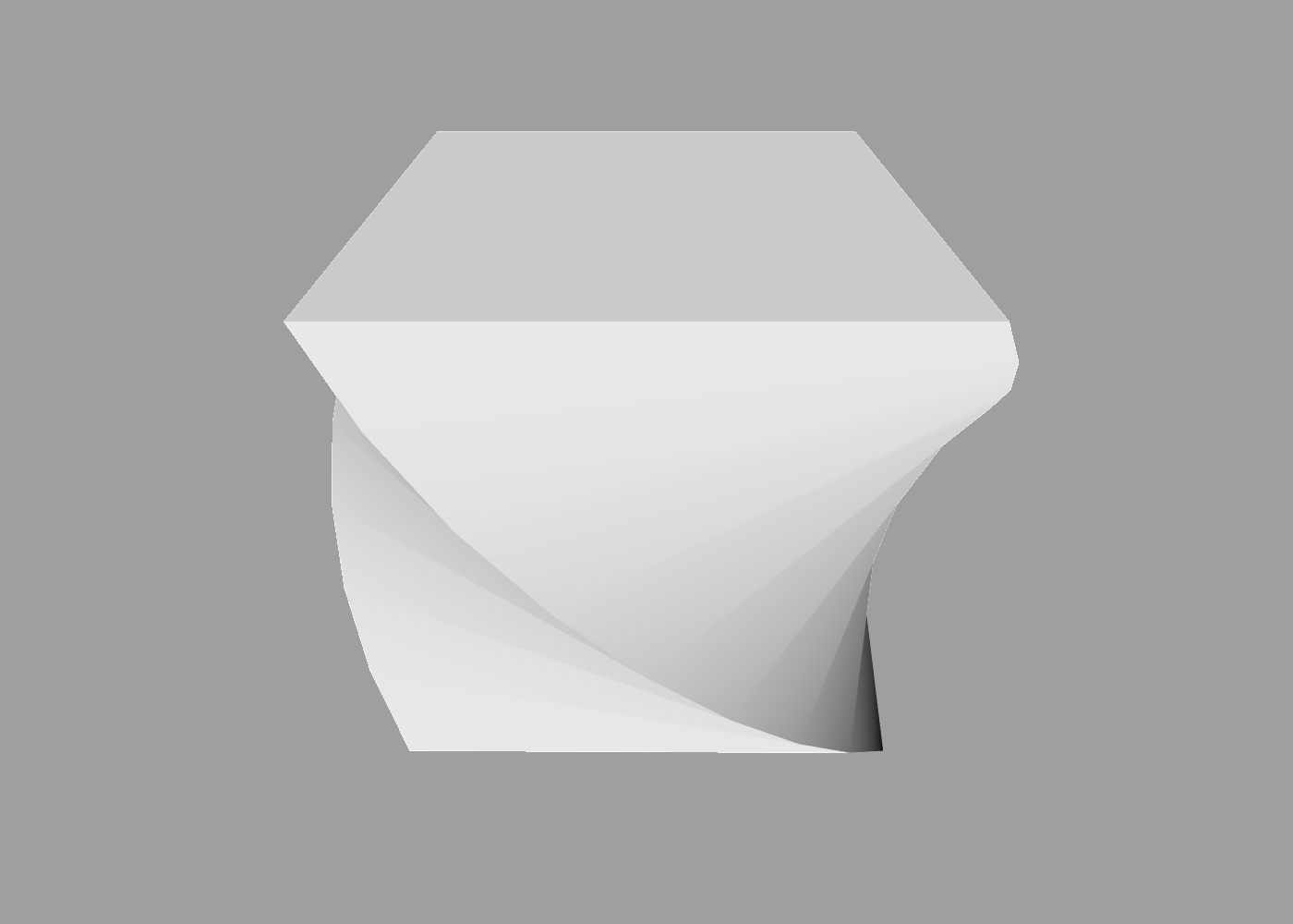
Twist uses the same half-turn units as the other rotation commands, so a twist of 0.5 equates to one quarter turn, or 90 degrees.
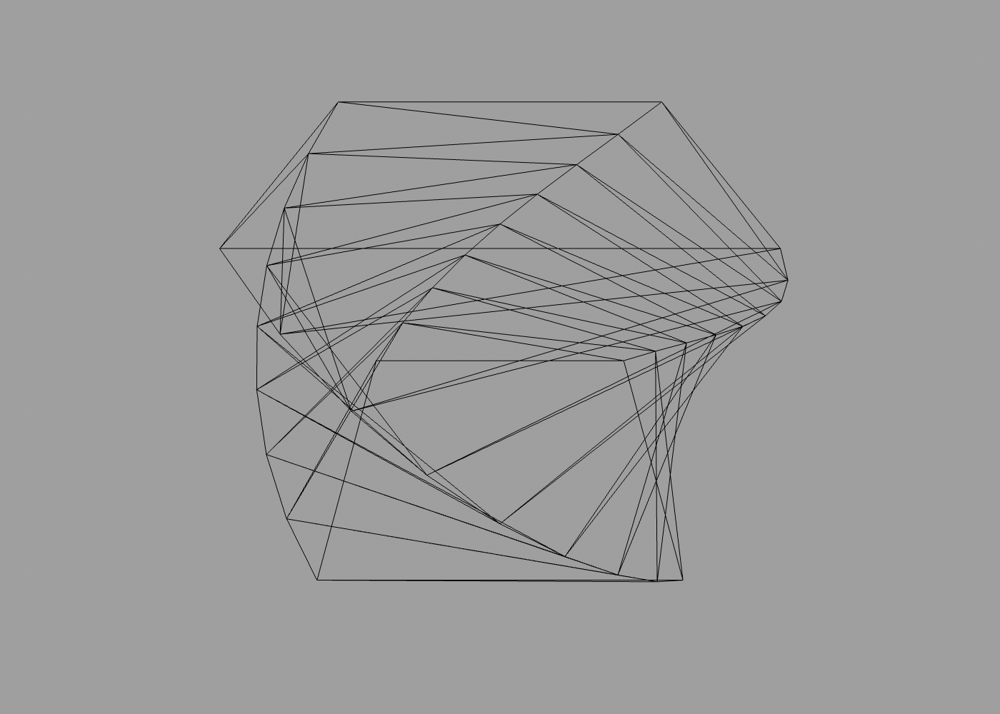
Applying a twist will automatically increase the number of cross sections in proportion to the current detail level to prevent distortion:
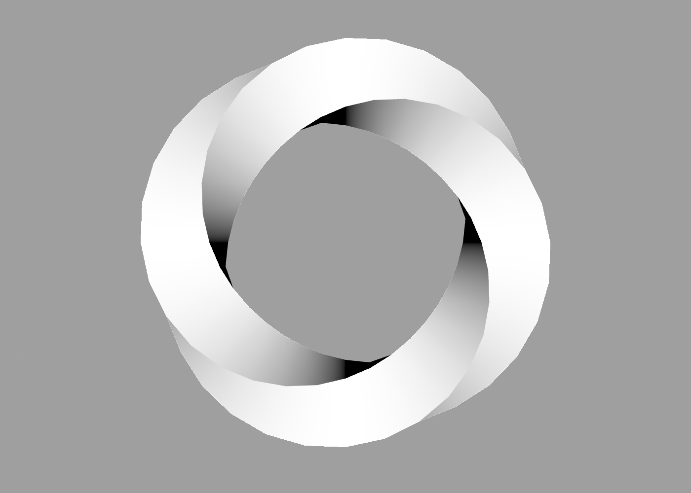
You can combine twist with the along property to twist a curved path:
extrude {
    square { size 0.2 }
    along circle
    twist 2
}
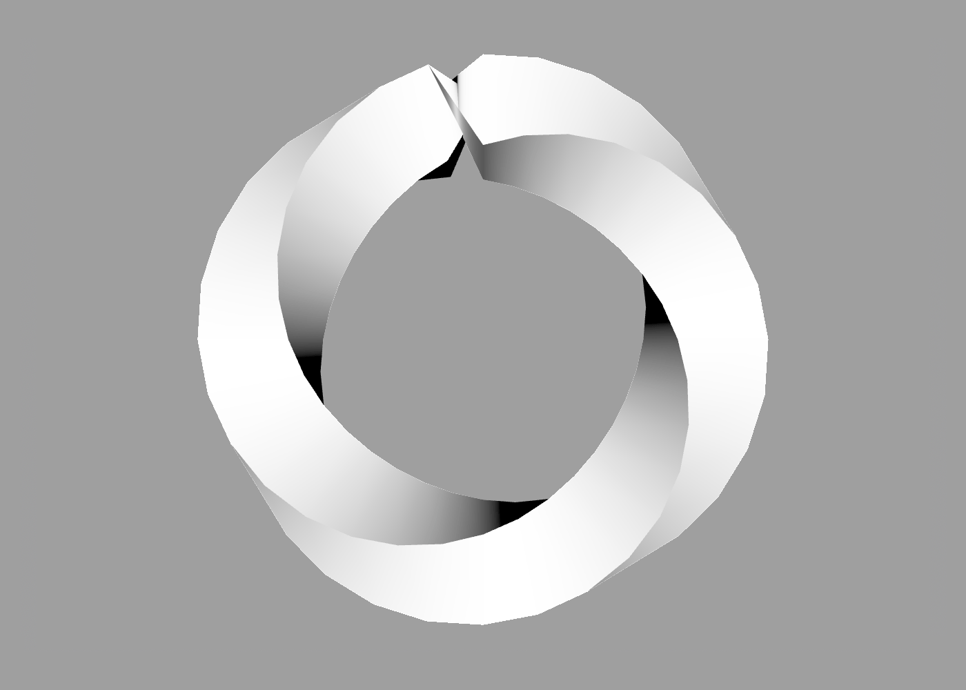
Note: when extruding along a closed path, you should always use a multiple of 2 (i.e. a full rotation) for the twist value to avoid an ugly seam:
Loft
The loft command is similar to extrude, but instead of taking a single cross-section path and extruding it by a fixed distance, loft accepts multiple cross-sections and then joins them together to form a solid shape.
For loft to work correctly, the specified paths must not all be located on the same plane, otherwise the resultant shape will be flat. You can either provide non-zero Z values for your path points, or use the translate command to space out your paths.
For example, the following code produces a prism equivalent to the extrusion example above:
loft {
    // triangle 1
    polygon { sides 3 }

    translate 0 0 2

    // triangle 2
    polygon { sides 3 }
}
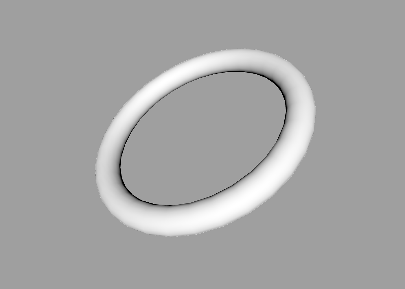
You can also apply rotations and scaling between cross sections, to create bends or curves. For example, the following code creates a torus:
define steps 32
define radius 1 // radius of ring

loft {
    for 0 to steps {
        circle { size 0.25 }
        rotate 0 0 -1/steps
        translate 0 0 (2 * pi * radius / steps)
        rotate 0 0 -1/steps
    }
}
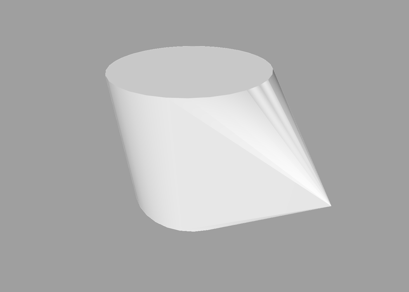
However, the real power of the loft command comes from the fact that you can use different cross-sections, and the resultant surface will be interpolated between them. For example, here is a shape whose cross-section is square at one end and circular at the other:
loft {
    square
    translate 0 0 1
    circle
}
Hull
The hull command works a bit like loft, in that it joins together multiple paths to form a solid surface. Here is the loft shape above, implemented using hull:
hull {
    square
    translate 0 0 1
    circle
}
So if hull and loft are the same, why have a separate command?
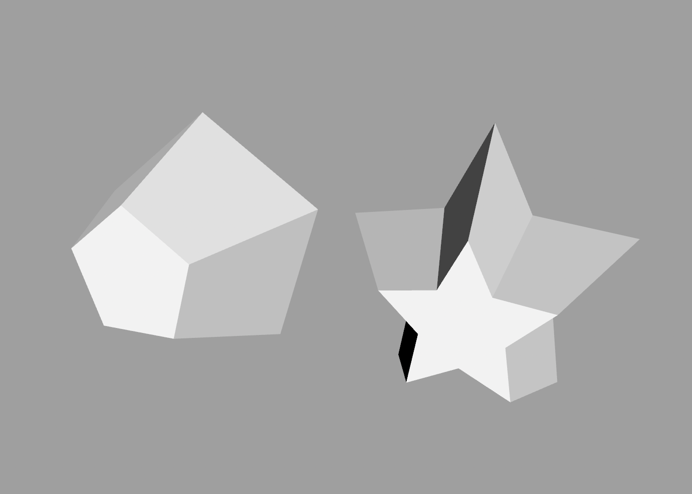
The difference is that rather than joining sections together in a tube, hull forms a tight skin around the outside of all its child shapes, known as a convex hull. To illustrate the difference, here is the hull of a star shape, vs a loft of the same shape:
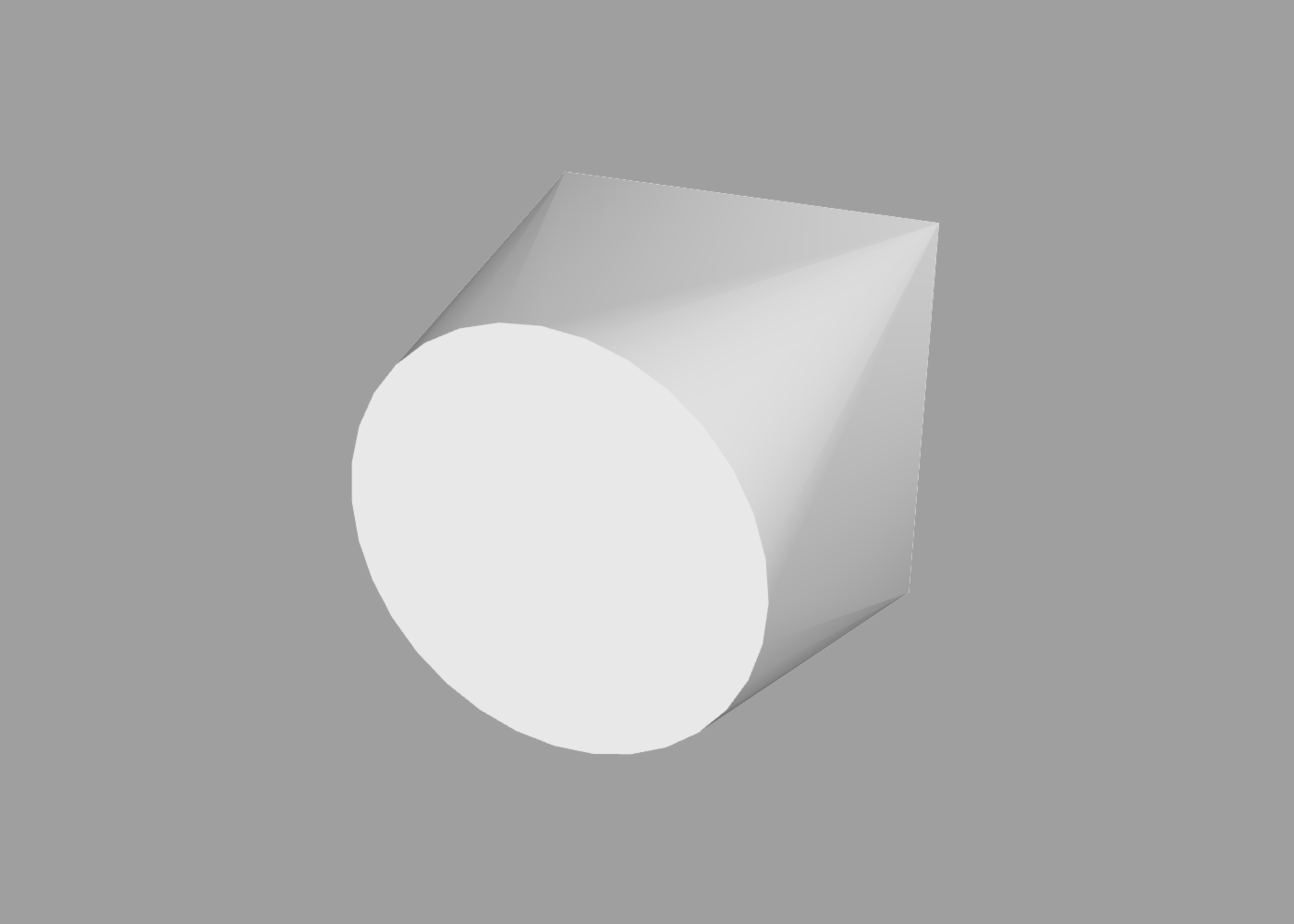
But the real power of the hull command is that it’s not limited to operating on paths. Unlike the other builders, you can create a hull around meshes, paths, points, or any combination. For example, here is a hull formed from a cylinder and a point:
hull {
    cylinder
    point 1 0 0
}
This allows for a lot of interesting shapes that would be hard to create using the other commands.
You might notice some odd stripes on the surface near the lip of the cylinder. As you may recall from the detail section, curved surfaces in ShapeScript are actually formed from straight-edged polygons, with lighting used to make them appear smooth.
When creating a hull from different shapes, the resultant surface normals aren’t always what you’d expect, which can result in lighting glitches like this. In some cases you can use the smoothing command to smooth out these discrepancies, like so:
smoothing 0.25
Minkowski
The minkowski command performs Minkowski Addition on two or more shapes.
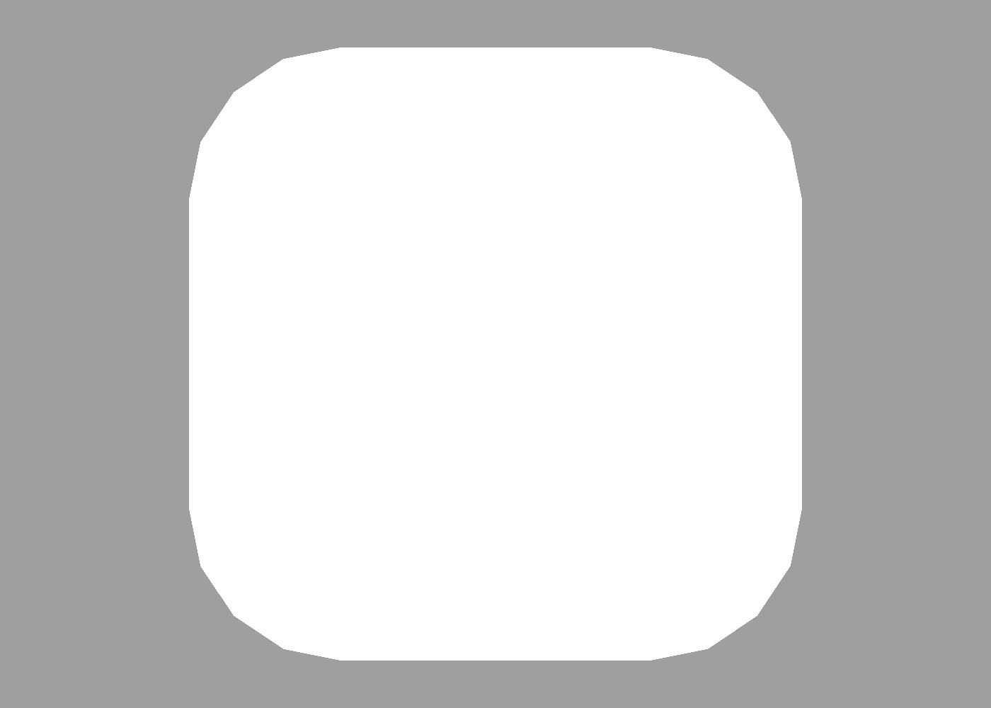
For example, the Minkowski sum of a circle and square is a rounded rectangle:
minkowski {
    circle
    square
}
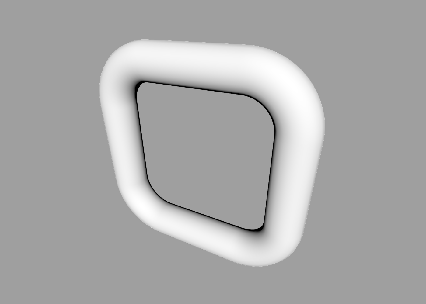
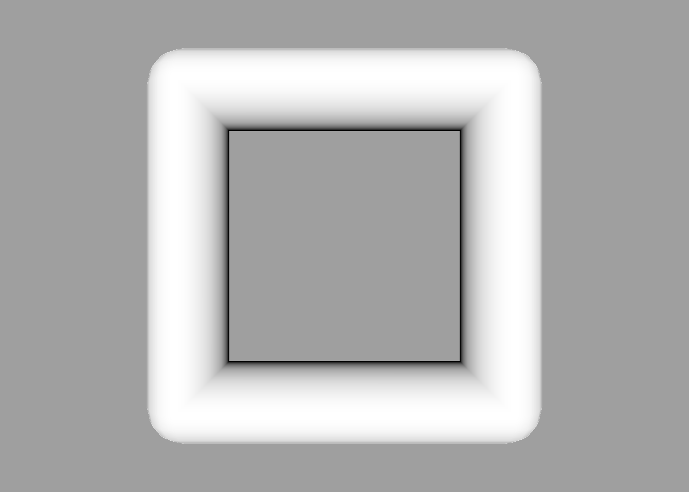
A smaller circle produces a rounded frame, since the sum of the radii no longer match the width of the square:
minkowski {
    circle { size 0.25 }
    square
}

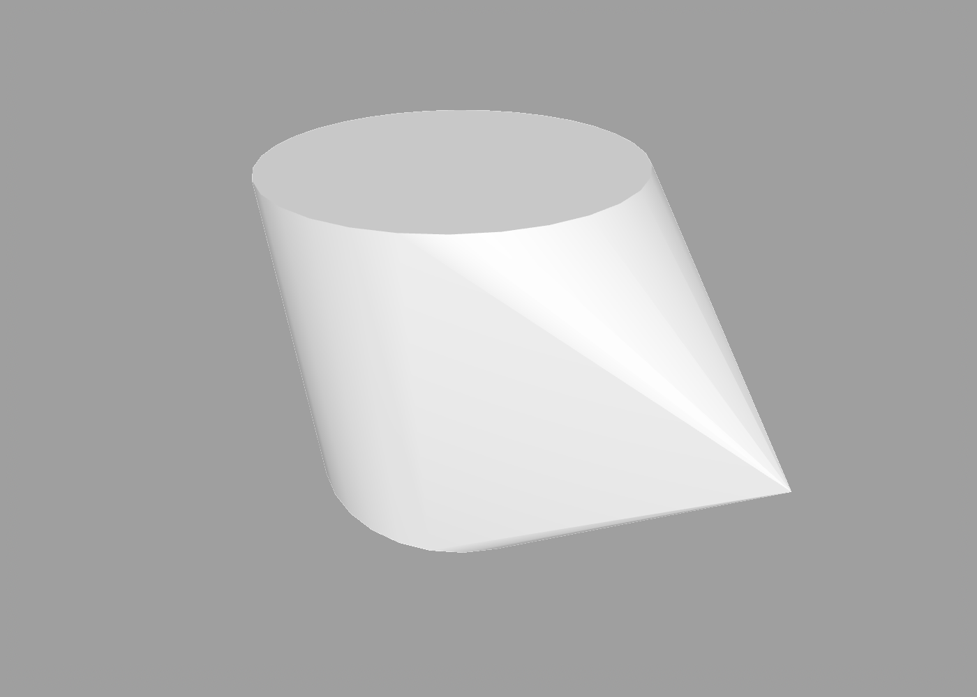
Like the hull command, minkowski works with meshes as well as paths. We can replace the circle with a sphere to bring the rounded rect into the third dimension:
minkowski {
    sphere { size 0.25 }
    square
}
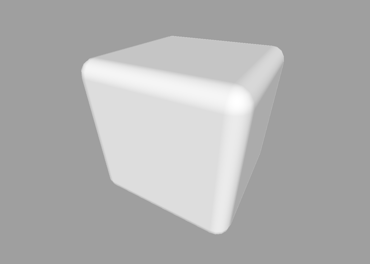
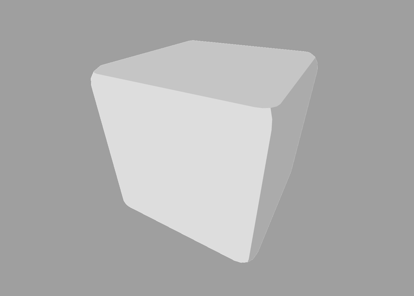
And if we also replace the square with a cube, we now get a rounded cube:
minkowski {
    sphere { size 0.25 }
    cube
}
Note: Minkowski addition is commutative, meaning that the order of inputs should not affect the result. However, the ShapeScript minkowski command can sometimes produce different results when the input includes paths or non-convex meshes due to various optimizations.
The order of child shapes can also affect how materials, colors and vertex normals are applied. If we reverse the order of the sphere and cube in the previous example, the actual shape is the same but the vertex normals from the cube are more dominant in the output, making it appear like there are seams:
minkowski {
    cube
    sphere { size 0.25 }
}
You can correct this using the smoothing command:
minkowski {
    cube
    sphere { size 0.25 }
    smoothing 0.25
}
Index | Next: Constructive Solid Geometry